


Part 2 - Components of Hydraulic Systems
author: MSc. Tobiasz Gola | Sc. D Piotr Rosikowski

Each hydraulic system is made up of components that perform an appropriate function in the system and their selection depends on the task that a given system must perform. In most cases, hydraulic power units consist of the components shown below.
Fluid tanks
A component of each machine or hydraulic device is a working medium hydraulic oil tank. Its primary task is to collect the necessary amount of hydraulic oil, taking into account the variable volume of actuators during the working cycle. In addition, the task of the tank is:
- hydraulic oil cooling
- precipitation of air from the working medium
- deposition of impurities
- separating the clean (suction) chamber from the dirty (output flow) chamber
- supporting structure function for other hydraulic components.
Figure 4 shows an example of a hydraulic oil tank assembly with accessories. The standard tank assembly includes the welded structure of the tank 1, equipped with at least one inspection cover 5 that enables cleaning the tank, drain valve 4 for complete emptying of the tank, oil level indicator 3, filler filter with air filter 6 and return filter 7, preventing before system contaminants enter the tank. Additionally, depending on the construction, the tank unit can be equipped with a pump unit (electric motor + pump) 2, a water-oil cooler 8, a supporting structure 9, to which additional hydraulic elements 10 can be mounted, and a control cabinet 11.
In most cases, the welded structures of tanks are standardized and have the following features:
- made of steel sheets,
- rigid, regular structure which is the basis for the installation of the pump-motor unit and elements of the hydraulic system,
- the side edges of the walls form a bath for oil escaping during the replacement of built-in elements,
- slope of the bottom of the tank, so that dirt particles settle at the lowest point and are not sucked by the pump,
- the dirty oil drain plug is located at the lowest point,
- the clearance between the tank and the ground allows good air circulation (good cooling of the bottom of the tank) as well as the transport of the tank with a forklift.
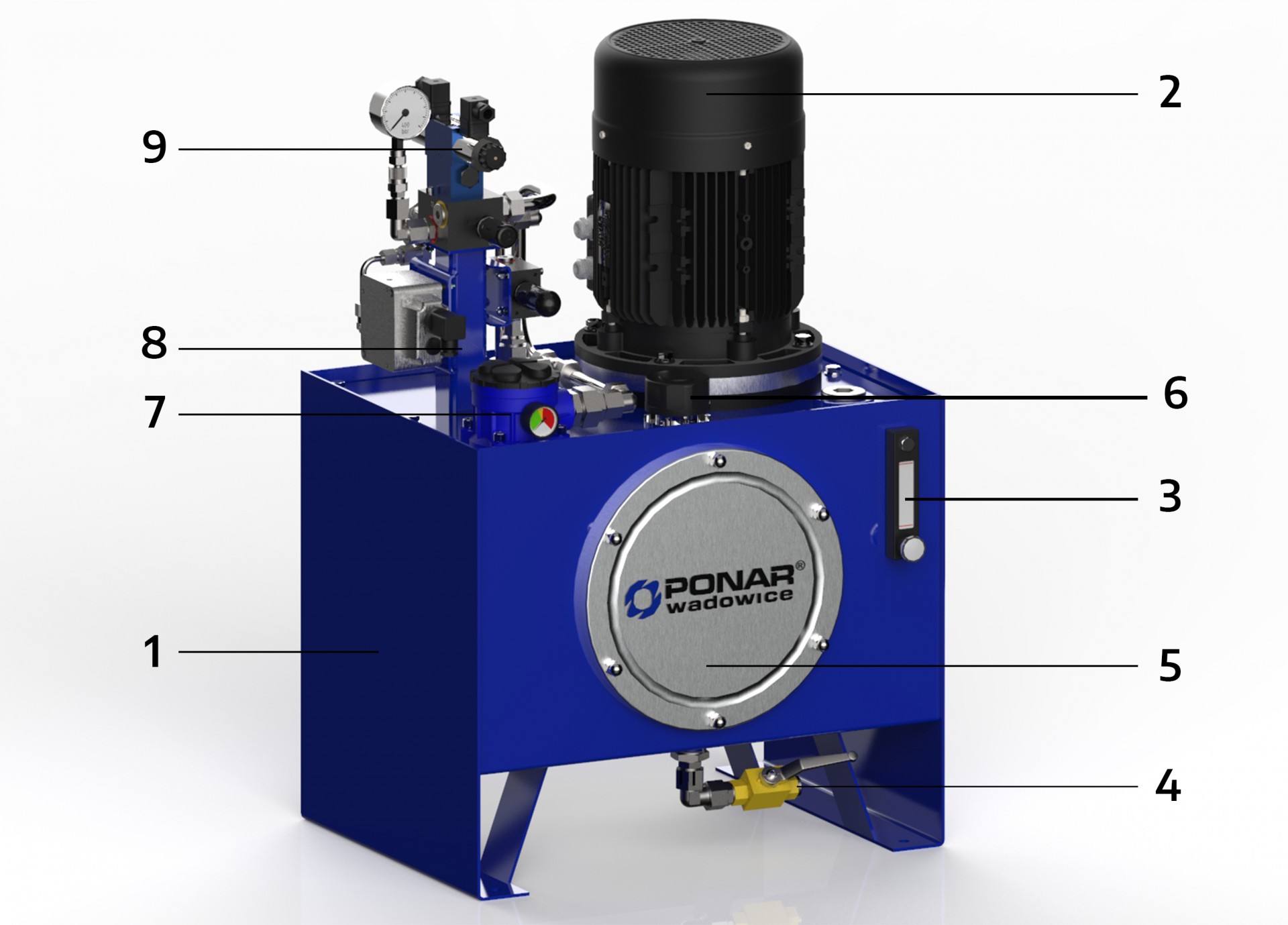
Figure 4. Hydraulic oil tank assembly with accessories: 1 - oil tank, 2 - pump unit, 3 - oil level indicator, 4 - drain valve, 5 - tank inspection cover, 6 - filler filter with air filter, 7 - return filter, 8 - supporting structure for assembly of hydraulic elements, 9 - additional hydraulic elements
There is dissolved air in the hydraulic oil, which must be precipitated out as bubbles. In order to facilitate this process, the tank should be designed in a way that the point of oil return is as far as possible from the place where the oil is sucked in by the pumps. If, due to the limited space in the machine, the hydraulic tank is small and the above-mentioned places are relatively close to each other, there is a high probability that the pump will suck in non-gas-free and turbulent oil, which may lead to its incorrect operation.
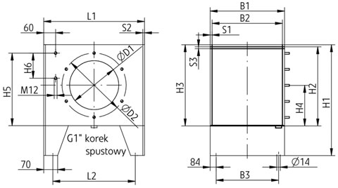
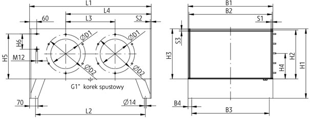

Figure 5. Overall dimensions of standard tanks depending on the required volume
The partitions are made in the form of thin sheets welded in the middle of the tank, so that they are forming a kind of labyrinth. Often, these partitions are also equipped with nets, which additionally trap air bubbles. Moreover, in order to prevent the oil from foaming, all drains to the tank must be directed under the oil level, therefore drainage pipes should be used inside the tank which is shown in figure 6.
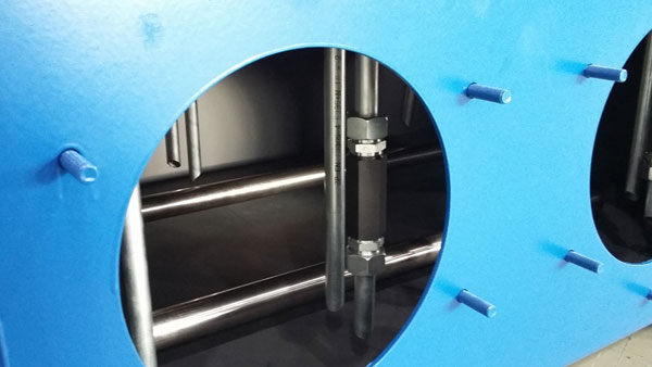
Figure. 6. Drain pipes in the tank
Motor-pump assembly
The basic element of each unit is a pump. Its task is to convert the mechanical energy supplied from the outside into the energy of the pressure of the working fluid. The principle of operation of the pump consists of forcing doses of liquid from the suction to the supply space by means of displacement elements. The size of the dose is determined by the dimensions of the displacement chamber. A necessary condition for the operation of pumps is a tight separation of the suction and supply space and the tightness between the chamber and the displacement element.
In modern hydrostatic systems, various design solutions of pumps are found.
Depending on the type of movement of the displacement elements, the pumps can be classified as follows:
Pumps with rotary motion of displacement elements.
- Gear pumps
- external gear pumps
- with straight teeth
- with oblique teeth
- internal gear pumps
- with straight teeth
- with special and straight teeth – gerotor
- external gear pumps
- Screw pumps
- Vane pumps
- with rotating vanes
- with non-rotating vanes
Pumps with reciprocating movement of displacement elements (piston pumps).
- Inline pumps
- Radial pumps
- with rotating pistons
- with non-rotating pistons
- Axial pumps
- with a tilted rotor
- with a tilted disc
- with a rotating disc
- with a non-rotating disc
The full range of pumps available at PONAR Wadowice S.A. can be found on our website.
Depending on the possibility of changing the displacement during operation, we can divide the pumps as follows:
· Fixed displacement pumps
· Variable (adjustable) displacement pumps.
The possibility of changing the efficiency during pump operation is related to its design solution and is considered only at a constant rotational speed of the drive shaft. For these reasons, gear and screw pumps as well as multi-piston in-line pumps are built only as fixed displacement units, while other types of pumps can be built in both variants, i.e., with constant or variable (adjustable) displacement.
Figure 7 shows the basic graphic symbols of the pumps: fixed and variable displacement. As already mentioned, the graphic symbols do not specify the design features, but only the functional properties of the hydraulic elements, in this case the issue concerns the stability or variability of the pressing direction and the constancy or variability of their performance.
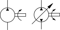
Figure 7. Basic graphic symbols of pumps: on the left - symbol of a unidirectional fixed displacement pump on the right - a symbol of a bi-directional variable displacement pump; own elaboration Figure 8 Pump units with vane pumps
Frames and front plates for fastening hydraulic components
Each of the power units has built-in hydraulic elements (discussed in detail in other articles of the Compendium of Power Hydraulics PONAR Wadowice). Selected methods of assembling these elements on aggregates manufactured by PONAR Wadowice are presented below.

Figure 10. Unit with stacked valves.
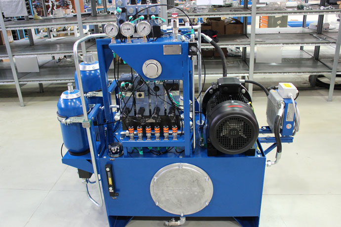
Figure 11. Hydraulic unit with a pump unit installed on the tank, integrated with an air-oil cooler and hydraulic accumulator.
Full offer od hydraulic systems can you see at our website www.ponar-wadowice.pl.
LET'S BE IN TOUCH!
EXPORT DEPARTMENT
tel. +48 33 488 28 20-29
e-mail: export@ponar-wadowice.pl