


Pressure control valves
author: Sc. D Janusz Rajda

Pressure control valves, generally speaking, are those whose operation and performance of a specific function takes place after the working fluid reaches the pressure set on the valve. Most often, the task of pressure hydraulic valves is to limit or maintain a certain value of the pressure of the working fluid in the hydraulic system.
Due to the function performed in the hydraulic system, we can distinguish: pressure relief valves, pressure reducing valves, pressure relief/reducing valves, pressure sequence valves and unloading valves which are often referred to as accumulator valves and have a structurally programmed (or adjustable) hysteresis. Pressure relief valves are used to limit the pressure in the entire hydraulic system, or in its part, by releasing excess working liquid to the "T" drain line (e.g., to a tank). The pressure relief valve limits the pressure in the system from its "P" inlet side. Pressure relief valves are connected in parallel to the pressure line "P" and the drain line "T".
The pressure relief valve presented in the drawing below is a direct-acting valve, i.e., the force of the setting spring (2) of the adjusting element (3) acts on the working element of the valve (poppet (5)) which directly controls the main stream of working fluid. The pressure relief valve, shown in the figure below, is a cartridge-mounted valve, which means that for its installation in the hydraulic system, dedicated body with an appropriate cavity for its installation (screwing in) is needed.
Examples of direct acting pressure relief vales in our offer are: DBD6,10,20, UZPD4,6,30 and many others. A special case of a pressure relief valve is a safety valve that meets certain legal requirements, declared by the manufacturer on the basis of a certificate issued by a notified body. These valves are delivered with a set opening pressure value (secured with a seal) and are identified by a given serial number.

The next figure shows a valve with the same function but indirect action.
The difference is that the spring (3) of the setting element (5) acts on the poppet (6), of the so-called pilot valve, the opening of which causes the flow through the control nozzle (9) and, consequently, a pressure drop in the spring chamber (7) of the main valve, which enables the displacement of the piston (4) in the direction of opening the main flow path from the pressure line "P" to the drain line " T ". This allows the control of valve elements with large passage diameters and, as a result, greater flow rates of the working fluid, without the need to install very large springs and settings with appropriately large dimensions. Examples of indirect action pressure relief valves in our offer include: DB10,20,30, UZPS4,6,10,32 and many others.
This principle of indirect control is used in many other types of pressure relief valves.
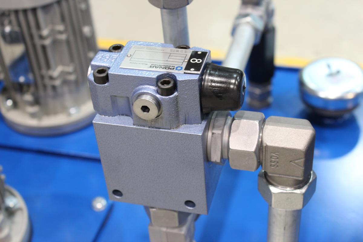
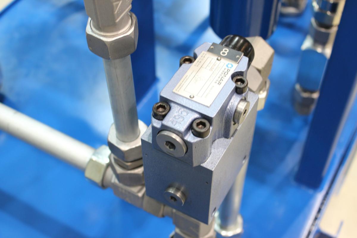
The valve shown in the drawing below is intended for subplate mounting, meaning that its body has communication and assembly holes with a standardized configuration, and its installation in the hydraulic system consists in screwing it to an individual subplate or a specially made block.

The function of the pressure reducing valve is to limit the pressure of the working fluid in the part of the hydraulic system on its outlet side, while on the inlet side there is a higher pressure, and it is connected in series in a given part of the system.
The pressure relief/reducing valve has an additional overflow function and protects the part of the hydraulic system against pressure increase from the outlet side, caused e.g., by external force on the actuator. The pressure relief/reducing valve shown in the figure below is an indirect action valve and uses the principle of operation described above (it is a cartridge valve)
Other examples of pressure relief/reducing valves in our offer are: DR10,20,30, UZCP10, UZCS6,10, UZRC6,10 and many others.

The role of the pressure sequence valves is to open the flow path to a specific part of the hydraulic system after reaching the set pressure at the valve inlet. It enables the realization of the assumed sequence of operation of the system as a function of the pressure value in the system, e.g. safe connection of the parts of the hydraulic system controlling the machining functions of the workpiece, only after reaching the required pressure necessary for stable clamping of the workpiece in the chuck. The figure shows an indirect action pressure sequence valve. In our offer it is also possible to find other examples of pressure sequence valves, e.g. UZK10,20,30, UZKC6,10, UZKS25 and many others.

Unloading valves are among the more complicated ones of pressure valves, because in principle they operate cyclically (automatically) at a certain pressure hysteresis, the lower the operating pressure hysteresis, the greater performance requirements are placed on the elements of these valves. These valves are most often used in hydraulic systems in which the hydraulic accumulator is periodically charged to a certain pressure value equal to the pressure set on the valve, after which the pump supplying the system is unloaded. After taking a certain volume of the working medium from the accumulator, which is manifested by a pressure drop on the accumulator side by a specified value (operating hysteresis value), the valve automatically closes the drainage path and allows the hydraulic accumulator to be charged again. The hysteresis value of this type of valves is usually constant ("embedded" in the structure) and when selecting a valve for a hydraulic system, its value must be determined in advance. Examples of such valves in our offer are: UZOP6, UZOP10,20,30 and others.
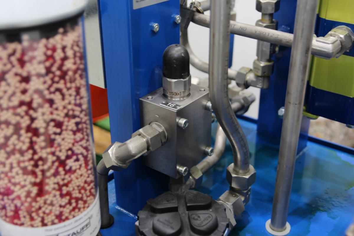
The figure below shows a typical unloading valve for the application described above.

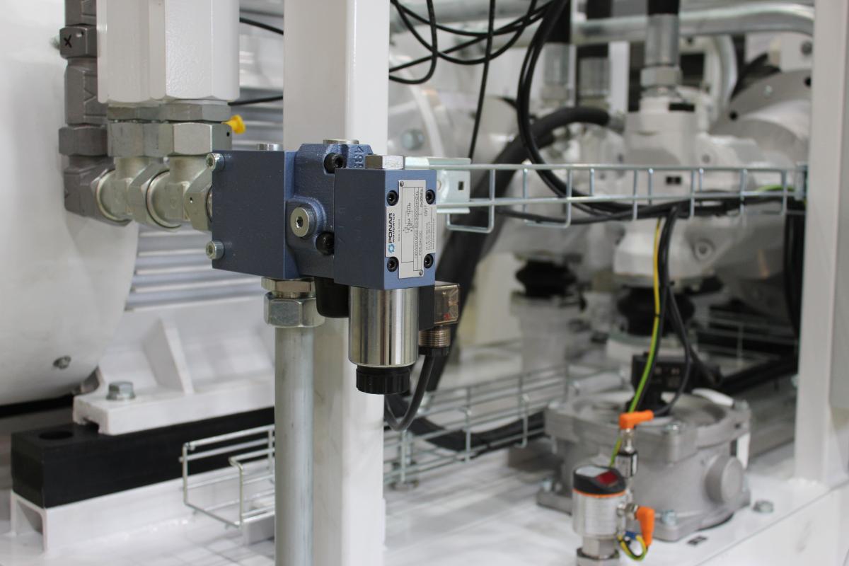
However, there are more complicated design solutions of this type of valves that allow for a stepless setting of the hysteresis of their operation. The valve with this function is shown in the figure below:
The main setting (6) is used to set the operating pressure, while the auxiliary setting (5) is used to set the operating hysteresis. An example of this type of solution in our offer are UZOP10,20,30_NH valves.

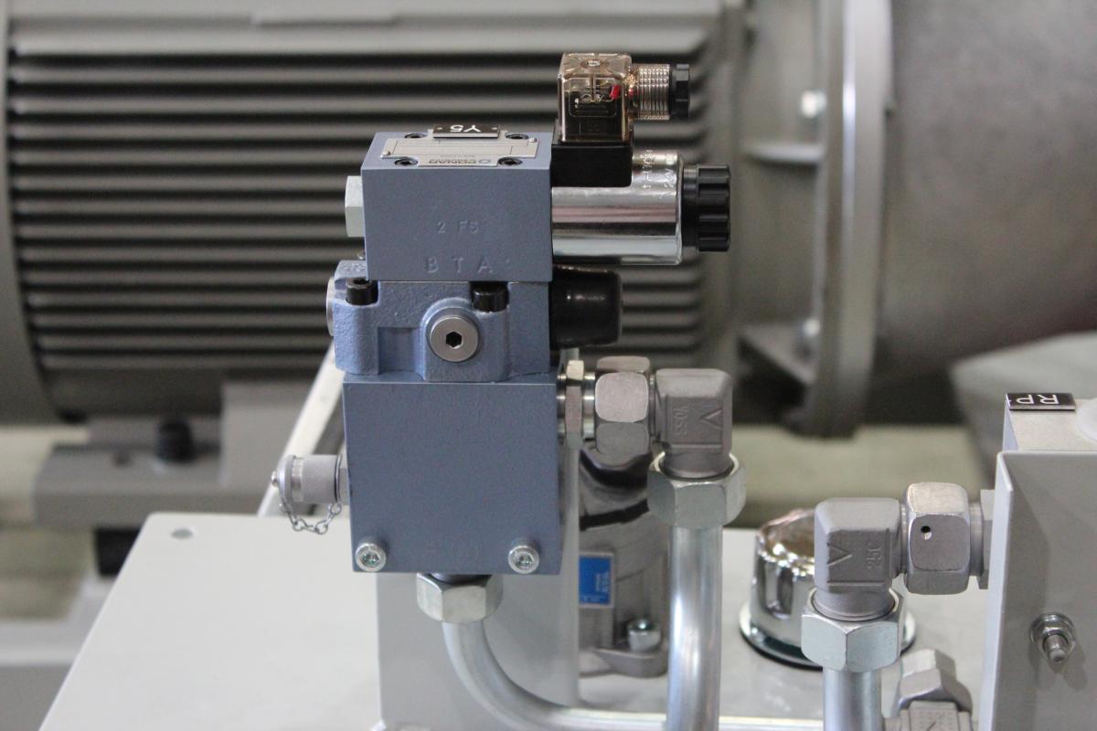
In the exemplary pressure valves described above, the setting is made by a suitable value of the preload force of the spring, e.g., by means of a screw. When replacing the spring charging system with a proportional electromagnet, the force of which can be adjusted by the value of the supply current, the pressure valve is called a proportional pressure valve (example below).
There are also solutions in which the spring force of the setting of the proportional pressure valve can be changed in other ways, e.g., by means of a helical gearbox and a stepper motor.
The full range of pressure control valves, including proportional valves, may be found on our website.
Let us be in touch!
EXPORT DEPARTMENT
tel. +48 33 488 28 20-29
e-mail: export@ponar-wadowice.pl
Gallery